Background Information
This section gives some incidental background to the products made available.
Model Railway Operation
The first need was to produce flexible means of controlling a layout. This gave rise to a lever frame design that reflected the prototype approach.
The first lever frame was a GEM product used on the first Eastwell layout - then known as Sherdington. It used an aluminium top plate which wore quickly and needed replacing This was primarily because the method of operation of the points on the layout that was wire in tube used micro-switches linked at the points. The micro-switches used a farly heavy return spring which put too much pressure on the aluminium.
This was replaced by a lever frame made from "O" gauge rail made by Mike Bell. It had a weak point which was the hole drilled through the rail. The rail broke during operation and this system also needed replacing.
The next version used early GPO switchboard toggle switches linked to the switch lever. This enabled extra circuits to be included such as those used to operate signals. However these toggle switches were in short supply - they only came to the surplus store outlets as electronic telephone exchanges replaced the manual ones.
The next lever frame required was for the Crusher Plant. This was labouriosly hand built by Mike Chaney. Although it worked well a more efficient system was required. A trail lever was made using an over centre spring to hold the lever in place and an integral micro-switch, also hand built by a trainee silver-smith Chris Clark.
The Coleorton layout used momentary contact electric switches, which were none too reliable and required extra electric contacts for track power switching. But it is impossible to tell the lie of points unless every point is reset before any train movement is attempted when control is via centre biased switches.
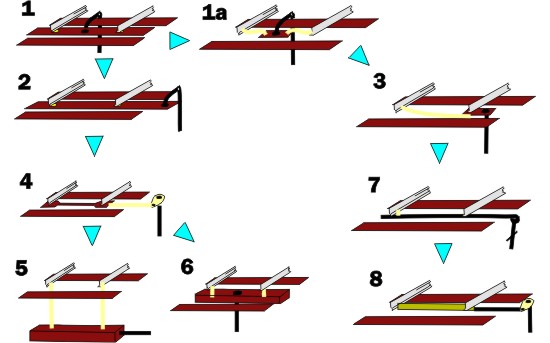
The first version of the lever frame included electrical switches that needed to be made up. This was not successful and was dropped in the second version. This version included a fixing point for manufactured push button switches. Following a visit to EXPO-South the lever frame was redesigned as version three to allow each lever to be fully assembled before mounting in the lever frame.
As version two was introduced due to customer demand a longer lever version was also made available.
When it was discovered nickel-silver sheet was available in the same thickness as brass so the lever frame levers were changed from brass to nickel-silver. To the original 6 lever frame shell 2 lever and 3 lever frame shells were introduced, allowing any size lever frame from 2 levers upwards could be supplied on demand, but this meant lever frames would need to be ordered.
For Colorton No.2 point and signal interlocking was needed to allow the signal box to control safe routes to be selected and signalled whilst leaving the colliery sidings to be operated independently.. But as the track plan for Coleorton No2 is none too prototypical it took many years to rationalise the locking frame arrangements.
As the points in the colliery were not exactly firmly locked in place - what was needed was a mechanism to allow the adjustment of point throw and hold the point switches independent of the lever frame. From that need arose the PALM unit.
Coupling Rolling Stock
Some of the Eastwell layout boards were very wide, so you had to have a long reach which limited the flexibility with operators. But the group had adopted "three link" couplings for several reasons - cheapness, lack of agreement on an auto-coupler and prototypical accuracy.
AMBIS is committed to using the almost invisible Alex Jackson coupler but were aware it has several disadvantages.
Railway Trackwork Details
A issue with point operation was the mechanism to move switch blades. On Eastwell a number of methods were tried .
Our first answer was to use a rivet in sleeper strip to replicate the function of a stretcher bar. The wooden sleeper strip provides insulation and the rivet if not firmly fixed will be able to rotate and thus provide for the angle change. However an extra sleeper in the track is not particularly protoypical and a method to connect that sleeper to the operating mechanism is required. What can happen is that loose track ballast can stop the "stretcher" moving easily, and the rivet fixing can rise and catch on the fixed stock rail stopping the switch blade closing properly.
Our second answer was to use a small piece of double sided PCB (Printed Circuit Board). This was fixed directly to one switch blade, on the underside a springy wire was soldered and then fixed to the other switch blade. This worked well except when the underside solder joint fractured (actually the PCB copper laminate - delaminated). This was impossible to fix during an exhibition.
Both these solutions used old technology, for example the PCB was thick fibreboard based. One day I came across a thin glass fibre based PCB. From this the first AMBIS stretcher bar kit was produced. What was needed was the connection between the thin PCB and the switch blade.
Version one was a complicated bit of origami needed to make up a box section. Version two followed which was a fold up version which looked more like the prototype connector. This is available in two sizes - smaller section rail such as code 75 bullhead and larger section rail such as flatbottom code 100 rail.
Another version for round stretchers was then introduced also making use of the same PCB material.
When Eastwell was built it was given hand levers made from flattened copper wire. These were quite easily damaged. AMBIS produced an etch version of hand levers which would hide a operating crank, and are more likely to damage track cleaner's hands, than be damaged themselves.
The point rodding and signal wires at Eastwell Station were time consuming items to produce from raw materials. AMBIS set out to make this easier and include the other components that were missing such as facing point locks.
Rolling Stock Components
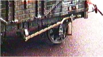
Much of the Eastwell rolling stock came from a bygone era. There were issues with missing brake levers which had been poorly glued on or were plastic mouldings that had become fragile and broken and brake blocks over 9 inches from the wheel that would never brake the wagon.
 A 4mm R-T-R wagon body with a replaced underframe and the first AMBIS brake levers and guides.
A 7mm scale plastic kit with test etches of the first series of brake levers and guides 
The original designs were to allow the whole brake lever assembly to work, if required. One reason was to allow wagons to be parked in sidings with their brakes on! Now to do this you need to disassemble the etch if you want the brakes to work.
To enable long wheelbase vehicles to negotiate small model railway scale curves we believe it is better to use rotating axles using a fixing point outside the wheelbase, not within it as is the case with the Clemison truck design. To reduce overhang of the vehicle and the possibility of wheels riding over the rail creating a derailment, the wagon axles should have a small radial movement.
On wheelbases under 12 feet this is not necessary, we have put standard EM gauge wagons up to 17 feet 6 inches long - with a 10 foot or 9 foot wheelbase and using (long) 3 link couplings around 12 inch or 300mm radius curves, built with a triangular track gauge, without problem, but longer wheelbase wagons and locomotives do have problems even on 20 inch or 500mm radius curves.
Motive Power Components
An early experiment for motive power improvements was to create an accurate looking driving wheel for the "austerity" tank engines, We had selected the ""Mike Sharman" wheelsets, before others became available. The illustration is the wheel having the overlay component fitted. In addition the gusset plates for fitting behind the buffer beams and etched steps were created along with the cottered coupling rods which were used on the predecessor range the "50550" class engine form Hunslet.

We have experimented with replacement windows for several other plastic model kits.. With regards to the (Dapol) Pug locomotive it is also necessary to enlarge the window opening to 6.6mm diameter. A problem with the Dapol model is that front and rear cabs have a different thickness so some further tailoring is necessary otherwise the new glazing will still be recessed.
Some locomotive names can be repeated by the same or different manufacturers or requested by different clients and these do not always use a standard nameplate style. Some names are fairly common such as "Jubilee"or use names of related persons to the locomotive owner e.g "Elizabeth" or the place the locomotive was located e.g "Kettering Furances". Quite often it appears names were transferred to successor locomotives by owners.
In general different manufacturers used different lettering and nameplates shapes, although some large fleet owners may have used a common design. Amongst the manufacturers Andrew Barclay seem to favour painted names but often used large cast makers plates. It is noticeable that at some point in time (after 1947) it appears new National Coal Board (NCB) locomotives had only painted not cast, nameplates. This seems most applicable to the "Austerity" design of 0-6-0ST produced by a number of different manufacturers.
Some nameplates produced are believed to be fictitious.
Scenery
The corrugated iron was first produced using take away food foil trays, flattened and smoothed then shaped using a serrated bottle top. The prospect of making many sheets this way for the Ironworks buildings in 1974/5 resulted an the late Bob Barrett producing a corrugating machine, whilst the late Alan Browning sourced rolls of flat aluminum foil.
After considerable use in 2007 a new 1.3mm profile machine was ordered, this time with the ability to make sheets higher (along the wave trough) than 32mm or 8 feet in 4mm to 1 foot scale. (this new machine became available in August 2013)
The early Eastwell buildings used coloured tape for window mullions. Time and damp storage facilities had meant the tape was falling off the windows and the cardboard roofs were bowing, requiring their replacement, or rebuilding. In general AMBIS would now suggest 2mm thick secondary double glazing material is used to form a building shell and window glazing. This clear plastic sheet is not an acrylic and can be worked as though it is a standard model makers plastic material.
If you model open windows seeing a very thick glazing material destroys any illusion being created, so we found a supply of clear 0.5 and 0.2mm thick glazing material.
A considerable range of windows, usually with metal frames was introduced following a commission for a set for "creamery building". This was then widened to include railway buildings and then ventured into vertical sash sliding windows - all made from 0.010 brass.
Once a fence post design was commissioned we started to look at other fences posts used on bridges and embankments and a a few other designs were added to the order book. This lead on to other lineside features such as mileposts, gradient posts and bridge plates. The success of being able to etch nameplates lead to the signal cabin name board product and thenthe other lineside features using lettering.
As part of a drawing became available we also ventured into street name plates which was felt could be used to enhance models in the vacinity of the railway.